As a homeschool family, we're always looking for projects that incorporate real-life events into education. For Halloween this year, I got the idea to have the boys design and build a fun (and maybe scary) photo booth.
Let's start at the end. Check out this video of the finished projoect, show-ready for Halloween (it was very successful, by the way, lots of great comments from neighbors, teens especially).
Concept
We started in late August with a basic conceptual design. The idea was to build a box (which we later starting calling "the machine") to contain the electronics. The machine would have mirror that people could use to check their pose, and it would snap several pictures. On the last picture, something unexpected (we hope) would happen--the mirror would drop away, revealing either an illuminated scare character, or a person in scary garb, then snap a photo of their surprise/fright. We wanted to have the option of a static figure or live person as the scare, so we could have the fun of doing the scares ourselves, or have it completely automated/unmanned.
The early details were really interesting to work out. We needed to figure out if we were going to have people sit or stand--we chose sit--and their average height when seated, distance from the camera, etc. Once we knew all of that, we figured out how big to make the box, the size and location of the mirror, and placement of the camera. Then we started building.
The Drop Door
We managed to get pretty close on our first attempt at the door. We knew the door had to drop freely, and as quietly as possibly. It had to "land" without destroying itself (smashing to a hard bottom), and be lifted back into "show-ready" position. The lifting mechanism had to be completely clear of the door and out of the way during the fall, and not restrict the fall in any way. It seemed the simplest approach was to use cables winding on a sheave to pull the door up. The cables would pass through eyelets in the sides of the door, and at the end of the cables would be some kind of hook or something to catch the eyelets and lift the door as the cable wound up.
For our prototype, we built a door face of 1/4" plywood backed by a frame (just 1x2 stock) to keep it stiff and flat (that thin plywood wants to bend and warp all kinds of ways) without getting too heavy. We sourced a couple of small pulleys, a 1/4" rod and some other hardware from McMaster-Carr, and a 12V gearbox motor that runs 30RPM from Amazon. Using plywood and stock we had around from other projects, we managed to cobble together the front face of the machine with a hole for the door/mirror, the door itself, and the necessary mounts for the motor and axle. Although we had purchased a flanged bearing to support the "far end" (opposite the motor) of the axle, we didn't use it because it was not a "pass through" bearing, it was a dead end, and we were uncertain about the ultimate dimensions of everything and wanted to avoid cutting the rod to a size that might be too short later. So, we 3D-printed a bearing for the end of the rod, and a spacer to slide on the rod to keep it positioned properly. The 1/4" diameter axle connects to the 8mm motor shaft through an adapter shaft coupling. Then we put the eyelets in our door, used some butcher string from the kitchen as our temporary lift cables, and tied 1" key rings from our "junk drawer" to the ends of our "cables" to catch the eyelets. We placed some cut pieces of a pool noodle at the bottom of the frame to soften the door's landing. A couple of manual drops from progressively greater heights confirmed our padding was sufficient.
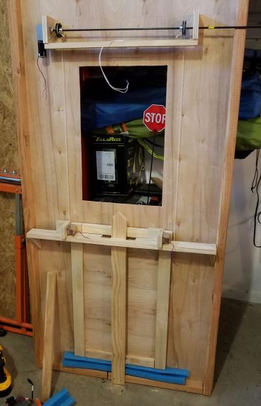
We then used a 12V SLA battery to run the motor and test the lift action. The motor speed and torque were perfect, and had no trouble lifting the door at an agreeable speed. In our earlier test drops of the door, we noticed it had a tendency to "bounce" on the pool noodle pieces and end up askew and off center. We needed to control the fall a bit more, and make sure that the door fell straight. So we conceived two set of guides and a rail to control lateral movement of the door during and after the fall. The guides were 3D-printed, and the rail was a scrap of 1x3. When the door was in the raised position, only the bottom guides would mate with the rail, but as the door fell, the top guides would engage the rail. The bottom guides were pretty simple--basically just blocks--but the top guides were shaped so that if the door fell slightly off-center, it would realign itself when it caught the guide. We also shaped the rail's top end to make that meeting of guide and rail more gentle. This worked fine. We could drop the door endlessly, and it would stay in line with the rail, and when it landed, come to rest straight and perfectly aligned.
The pulleys we bought were V-groove, and the string/cable would too often wedge itself in pretty tightly under the weight of the door when lifting. That would sometimes cause the cable to not come off the pulley smoothly when lowered--it would "catch" and start wrapping itself up again in the opposite direction rather than paying out neatly. The fix was quick and simple. We 3D-printed a pair of wide, flat drum sheaves, like large cranes use, onto which the cable would neatly wind itself. The drums were pre-printed with holes through which we could bolt them to the V-groove pulleys. Another problem solved. We also replaced the butcher string with micro-paracord--very strong but very thin and flexible.
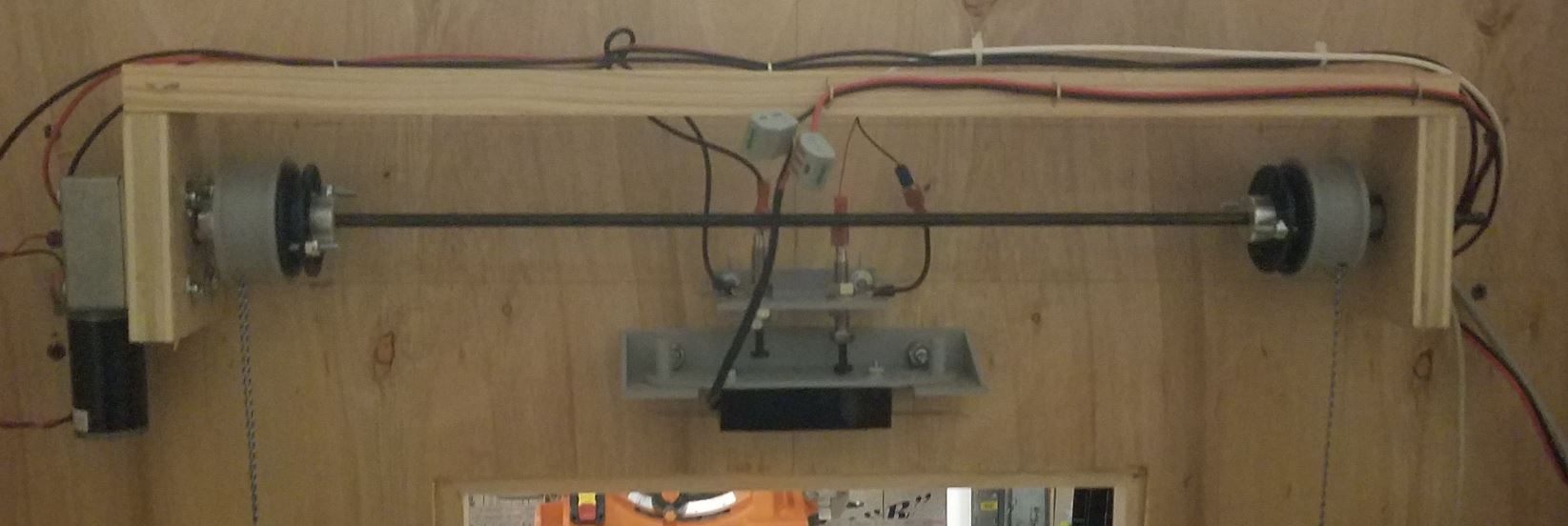
The next problem we solved was holding the door in "show" position and dropping it. Our first attempt was to use a pair of solenoids. You can see them in the picture above mounted to the horizontal rail just under the window. The solenoids would be extended and hold up the door in show position, and then when voltage was applied at the right moment, retract and release the door, allowing it to fall. That was all good in theory, but when we tested it, the solenoids could hold the door but not release it--the door was too heavy and the solenoids' pull insufficient to overcome the weight/friction. We went looking for beefier solenoids, but turned up very little that wasn't a bit pricey, and our confidence in that direction was shaken (what happened if one solenoid released but not the other?). But as we were searching for stronger solenoids, we found this magnetic lock. This is the type of lock often used to lock large glass doors in office buildings, or hold interior fire doors open (when released, the doors close automatically). A strong, efficient electromagnet, when energized, holds the door fast open or closed as the application requires. Cutting power to the electromagnet releases the hold. The lock is advertised to have 130lb holding force, more than enough for our little door to hang from, so we reasoned we could position it vertically and have the lock hold the door up until the perfect moment, then release and drop.
While we were waiting for the mag-lock to be delivered, we thought about how to mount it, and how to know when the door was in the right position. We had thought a lot about moving the door, but didn't spend much time trying to figure out where the door was, and so we solved these two problems together. We conceived and 3D-printed a mount for the mag-lock that had vertical "play"--we figured that motor shut-off is not instantaneous, so when you turn the motor off during a lift operation, there's a slight overshoot until the motor stops, and if we had a hard mounting position, we'd end up breaking it. So we designed a mount where the mag-lock was bolted to a plate that could slide vertically, lateral movement prevented by pins that went through holes in the plate. Above that, we mounted two plunger switches, one to send a signal to the Raspberry Pi that the door had reached the top position, and another to cut power to the motor altogether. This second one was a safety--if the Pi ignored the signal from the first switch for some reason, or didn't respond fast enough, the second switch would simply cut off the motor and prevent damage to the mount, pulleys, and motor (there's a video below that shows all of this operating).
When the mag-lock arrived, we put it all together and tried it out. Success! The mag-lock easily held the door. The release was smooth and quiet. And bonus, the mag-lock is very efficient, and uses a lot less power (<120ma when holding) than the solenoids, which have a significant current spike when they operate and inductive kick when they release.
The last big piece of the puzzle to solve at this point was motor control. We needed to run the motor forward and backward, and it's a 12V motor being controlled by a Raspberry Pi that runs at 3.3V. We needed an interface between, and relays were not going to be the answer (although I absolutely love relay logic and have done a lot of it, electronic switching is more than adequate here). Figuring that Adafruit had a solution, I quickly found their DC and Stepper Motor HAT for Raspberry Pi. I love Lady Ada's products, and this was perfect. Onward!
At this point, we were confident enough in our door design to start focusing on the software.
Software
The software put us in the path of a lot of firsts (for us). None of us had used the Raspberry Pi camera before. None of us had written more than a few lines of Python before. We had no idea how to play sounds, or show pictures on the screen. All we knew how to do was read and control the GPIO pins. So, starting with what we knew, we forged ahead in Python and started writing the code to control the door--detect position, run the motor forward and backward, etc. Installing the Adafruit software for their MotorHAT was first try no fail.
The first thing we tackled was showing messages on the screen. We wrote a simple jQuery-based page to pick up messages from a simple server that we wrote in Python. The server side could tell the page to display text or an image. The client would maintain a continuous connection to the server, waiting for a new message. When a message came, it processed it, did whatever was needed to the display, and then resumed waiting for the next message. The browser displaying the page (Chromium on RPi) was opened automatically in kiosk mode at (auto) login, so the display would always just come up ready to go, displaying a default "we're closed" message until the server side started accepting connections and telling to display something else.
Our first go at controlling the camera and taking pictures was using raspistill via call in the subprocess module. That was a choice of ignorance, because we didn't know otherwise how to control the camera. I knew there was a module for it, but there was so much to do and what we were doing worked, so we moved on. Eventually, as the software evolved, we found the Picamera module, and removed those subprocess calls.
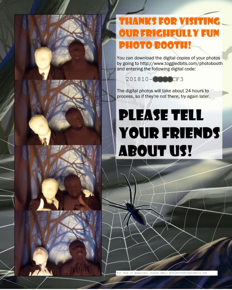
We found Pillow (the Python Imaging Library), which seemed to have all the tools we needed to take the grabbed captures, scale them, and arrange them into a new image as a photo strip. We then upped our game there a little by reasoning that we could load a canned image with nice graphics to place the images on, rather than just making a strip on piece of paper. We also decided to print a unique code on each image, so that visitors to our photo booth could later go a web site and download their photos and print additional copies.
We also discovered pygame, which we used just for sound. Its use for this purpose is very simple, basically just loading sound files and playing them on queue. In some places, we needed to wait for a sound to finish, to sync up with other activities. But it's nice having the library play everything asynchronously itself without the need to manage additional threads.
More Hardware
Eventually, all of the software pieces came together with some cohesion, and it was time to take the RPi off the desk and put it on "the machine." Hmm. New problem. How and where would we mount it? The camera cable is short, like 6", so we needed to mount the Pi close to the camera. We decided to 3D-print a shell for the Pi to live in, with mounts for both the camera and the Pi itself. After a couple of minor iterations in Fusion360, we had a shell with Pi and camera mounted.
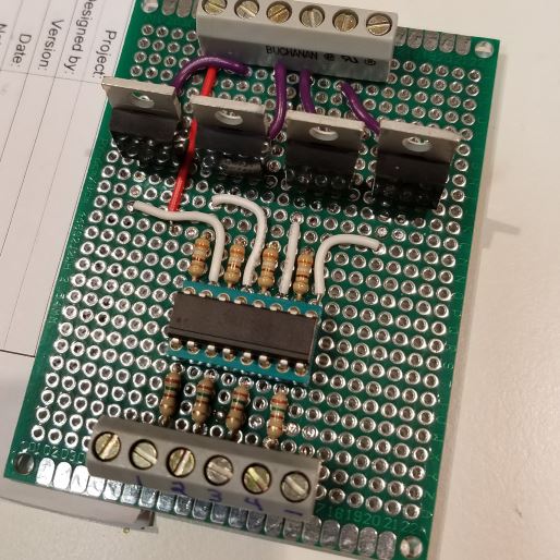
The next problem to solve was driving all of the lighting and effects loads, which are 12V, and some drawing many amps, from the 3.3V RPi GPIO pins that can only sink a few milliamps. To do this, we built on what we had learned building the RGB LED Strip project. For that project, we had used an Arduino to drive MOSFETs, which in turn drove 12V RGB LED strips. Using this design as a basis, we adapted it to 3.3V input. We decided that we would use optocouplers between the 3.3V and 12V side, to give the MOSFET gates a more decisive drive, and leave the option of controlling voltages higher than 12V (e.g. 24V or more, where Vgs max may then be exceeded for the device we're using, IRLB8721). We designed the circuit on paper, then moved it to Eagle and design a board for it, but didn't have time to get the boards fabricated before Halloween, so we built them on protoboards. On the bench, they worked fine. Our highest load would be the photographic lighting, at 36W each for two units (72W total) that we also built ourselves from extra LED strips we had laying around, and the boards handled that, no problem. The only thing we added to the circuit before the project was finished was a large diode across the mag-lock connection, to ensure that any inductive spike from the mag-lock didn't destroy the transistor. We used two driver boards, which have four channels each, for a total of eight channels (we used seven of them).
Input-wise, things were pretty easy: the project has only two inputs. The first is the "door up" limit switch, which is directly wired between a GPIO pin and ground (pin configured as input with pull-up), so that the pin reads 0 when the door is anywhere other than "up," and 1 when the door is up. The other input is a big red pushbutton used to start a photo session, wired the same way. Couldn't be simpler. The pushbutton has a separate lighting circuit to illuminate it, using 12V and controlled by a channel on our homebrew driver board.
A trip to the lumber yard for a few extra supplies to finish out the "box" of the machine, and we were ready to go. We cobbled in a 12V 100W power supply for the 12V loads, hooked everything up to our driver boards and the Adafruit MotorHAT, and fired up the RPi. No smoke! Everything pretty much worked at the high level, but without going into every detail, we spent a lot of time over several days combing out show timing and details, fine-tuning, and fixing bugs. We also started to pull some of the code, like the functions that controlled the door, out into modules of their own, so we could have stand-alone utilities for testing and controlling the door and other parts of the project.
Here's a video focusing on the operation of the door lift mechanism.
To enclose the booth, we simply used 1" PVC pipe to make a frame, and ordered some blackout curtains from Amazon.
Check out a test of the booth, still unfinished, running below. This was taken about a week before Halloween.
A Big Detail That Needed More Time
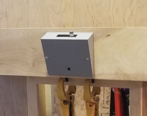
We focused so much on getting the booth up, running, and fitted, that an essential element of the finished product was left to the end, and would have benefited from more time: printing the photos. All along, the plan was to use our Brother MFC4710 color inkjet, "built in" to the booth. We made a stand for it, and a slot at just the right height with a 3D printed bezel for the printed photos to drop through. Mechanically, it was all fine. Software-wise, it was a disaster. I placed way too much confidence in CUPS, and given my past negative experiences with Linux printing in other environments, I'm not sure why. But anyway, my experience taught me that CUPS works great for the included device drivers, but ours was not one of those, and results are very much hit-or-miss when you start introducing manufacturer-supplied drivers for printers that are more than a few years old.
CUPS on the Raspberry Pi has especially sparse printer support, and could not support Brother's drivers because Brother only offers their drivers for i386, and RPi is ARM. And Brother doesn't provide source code, so building from source wasn't an option. After trying to convert the images to PostScript and getting them to the printer without a driver, which I also could not get working, plan C was to kludge a "print queue" on the RPi where the show software could drop a finished photo strip image into a directory (the "queue"), and a "queue runner" (shell script) would scp the image files to an Ubuntu server running in a VM on a system in my "lab." From there, another shell script would submit the image to a very current version of CUPS with the Brother driver installed. This worked fine until Halloween day. On the day, it stopped working, as again in my experience CUPS is sometimes given to do. And after wrestling with it for a couple of hours and making no progress, hands went up in the air and that last piece of automation was abandoned. On Halloween night, I sat in the dark behind the booth, on my laptop with the image folder open via Samba, and printed the finished images manually as the show software produced them.
On the Web
An important feature we wanted to have was the ability to download your photos, so visitors could print additional copies of their photo strip, and get all of the images used in the strip at full resolution. Since the boys weren't familiar with PHP, I cobbled this together the morning after Halloween. Our printed photo strips included a code, and the image filenames all contained that code, so it was easy to write a web UI to request the code, confirm it was valid, and find and present the images related to it.
Other Things
In the end, the photo booth ran great, except for the printing debacle, and one other bug which I could not iron out beforehand. Occasionally, without explanation, the RPi would make a sudden loud "pop" through the speakers when playing a sound, and there would be no audio after until the RPi was power cycled. I suspect there is some kind of I/O timing problem/race condition between audio and the camera, but it could easily be caused by something we're doing or not doing. It just didn't happen often enough to make it a high priority to find, but of course, it popped up once on our inaugural Halloween, necessitating a (mercifully quick) reboot mid-show. The guests were very patient.
What's Next
We've decided this is something we want to do every year, but we're going to change it up every year as well. Different themes, maybe some years with a scare, some years not, but basically always find something fun to do with it.
Operationally, here are the things on the hit list for version 2.0:
- Build the whole thing from extruded aluminum, and have solid panels instead of curtains.
- For any future version of the drop door, we can make the drop door track simpler and more reliable, with a simple aluminum channel guide.
- Find a way to print reliably to whatever printer; this probably means figuring out why PostScript didn't play nice, or creating our own simple printing system where we feed the image through a filter that writes directly to the printer.
- Although the booth can run without an operator, our booth had "scare" and "no scare" modes that I had to switch by touching or removing a file called "noscare"; it would be good to have an external interface for an operator/assistant to be able to switch show modes, start a show (a button in parallel with the big red button inside), and initiate a warm start or cold start.
- Super-nice addition to the above would be a UI (TFT screen?) that allows an operator/assistant to browse through completed images and reprint, since sometimes you have three people in the booth and they'd all like copies.
- Formalize all of the electronics to a board that connects to the RPi GPIO connector directly (and supplies power to the Pi).
- Find some way to get the camera more distant from the Pi.
- Video feed of what's going on inside the booth for people outside to watch.
Parts and Costs
- Raspberry Pi 3 B+ with v2 camera -- $35 + $30 = $65
- McMaster-Carr 9845T1 (qty 2) shaft coupling and 9845T11 spider, 4575N23 bearing (qty 2, not used), 1886K4 rotary shaft 1/4", 3060K14 V-belt pulleys -- $122
- Scrap plywood, 1x2 and 1x3 stock -- est. $60 (most of the plywood was B-2 or A-1; would be less if cheaper material used, at expense of appearance)
- Various 3D printed parts, most of one spool of gray Hatchbox PLA -- $22 (printed using Prusa i3 MK2)
- Uxcell 12V 30RPM Gearbox Motor (Amazon, no affiliate) -- $30
- Magnetic Lock (Amazon, no affiliate) -- $21
- Acrylic Safety Mirror 16x24 (Amazon, no affiliate) -- $44
- 1" PVC pipe and fittings (home center) -- $24
- Lexan sheet (18x24, home center) -- $22
- Blackout curtains (Amazon, no affiliate) -- $52
- White LED SM5050 strip (3m total length used) -- $30 (estimated, had 'em laying around)
- RGB LED strip (0.5m length used) -- $3 (estimated, had 'em laying around)
- Mean Well 12V 100W power supply (DigiKey) -- $18
- Adafruit DC and Stepper Motor Hat for RPi -- $22
- Adafruit Massive Arcade Button (red, 100mm) -- $10
- Parts for two driver boards, including LTV-847 Quad Optocoupler, protoboards, 8 IRLB8721 MOSFETs, handful of 1/4W resistors, terminal blocks -- $15 total
- Misc. hardware, connectors (FastOn, etc.), wire -- $25
TOTAL: $525